_____________________________________________________________________________________________________________________________________________________________________________
Badnixie.com
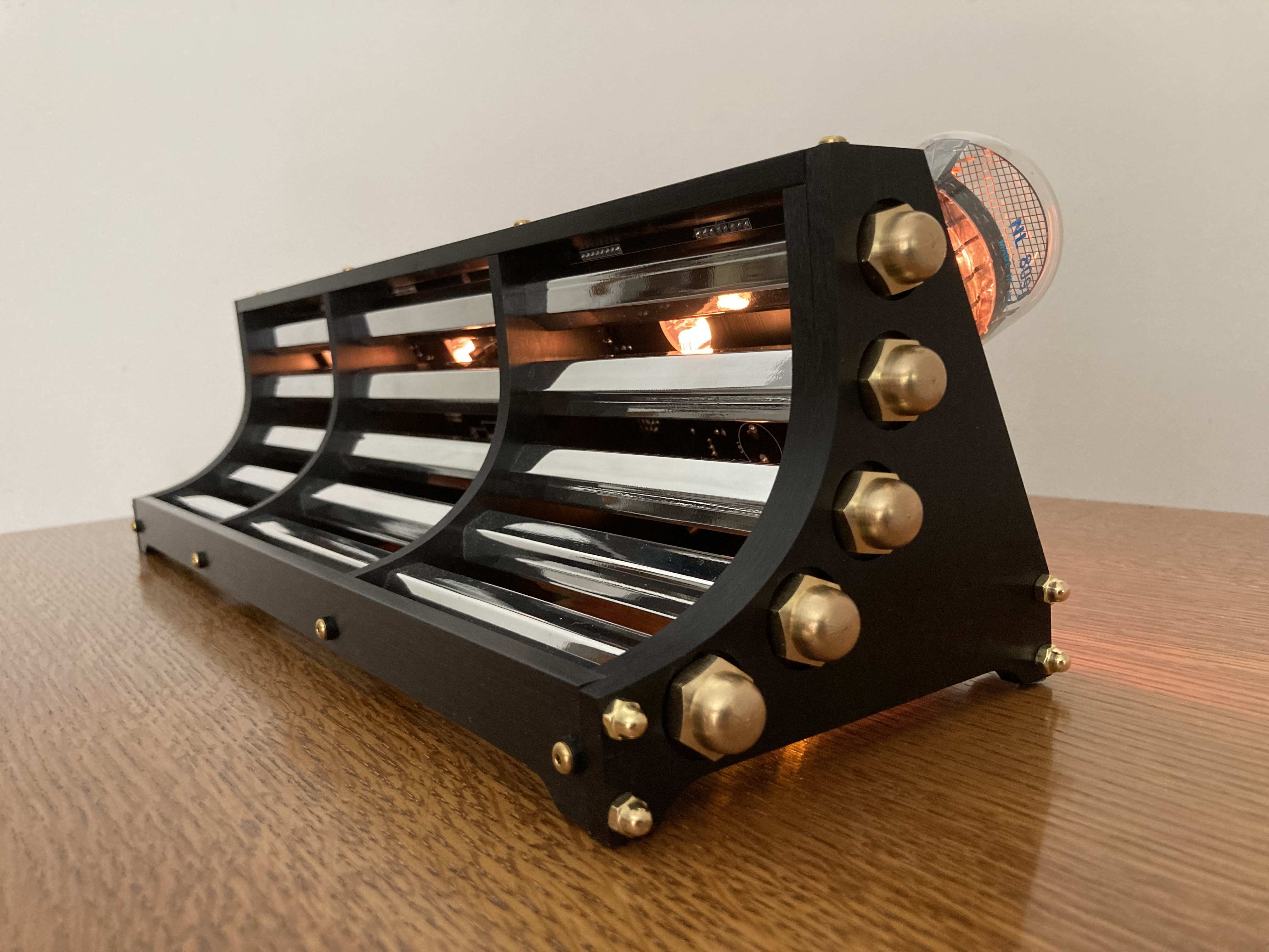
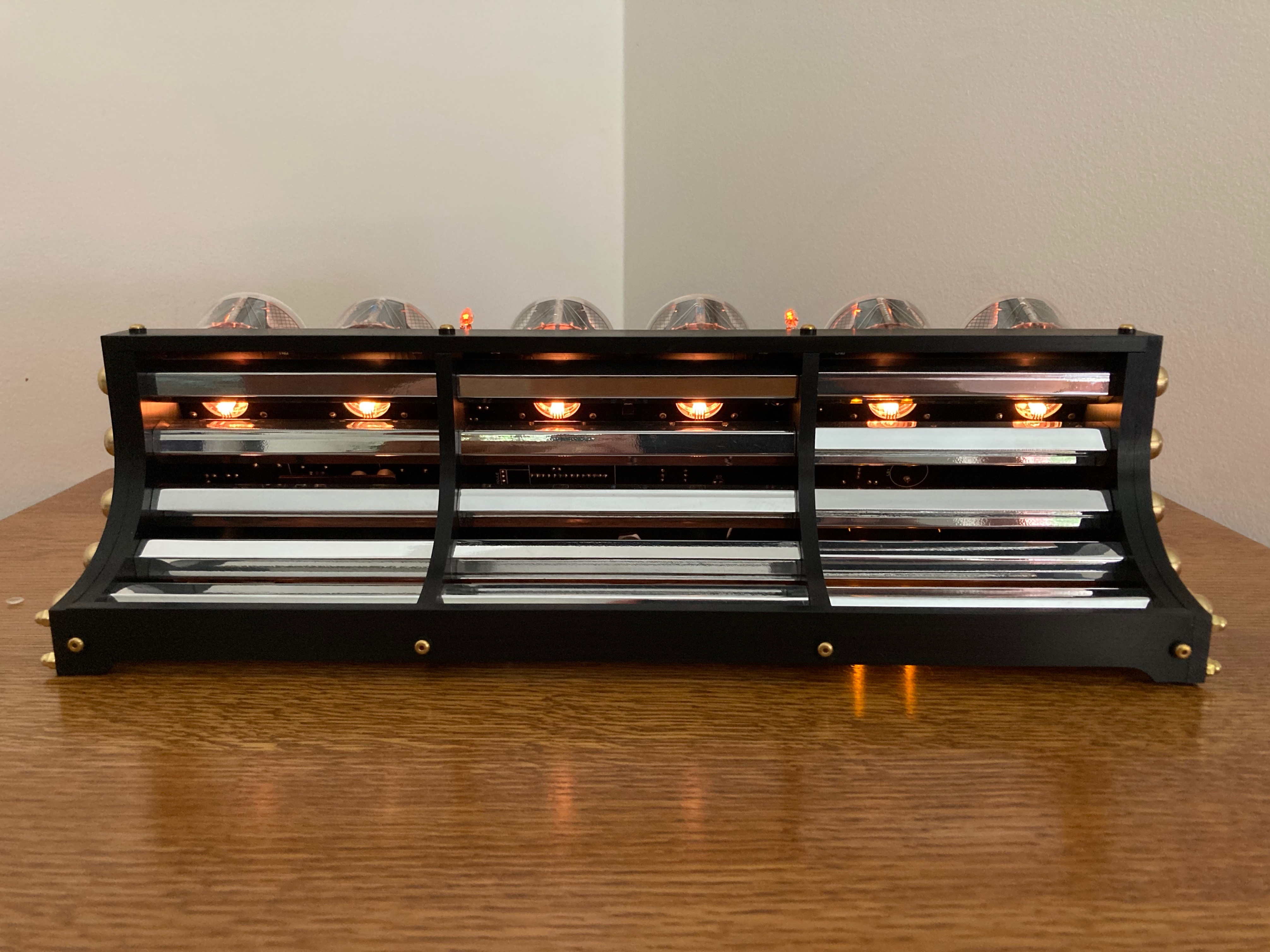
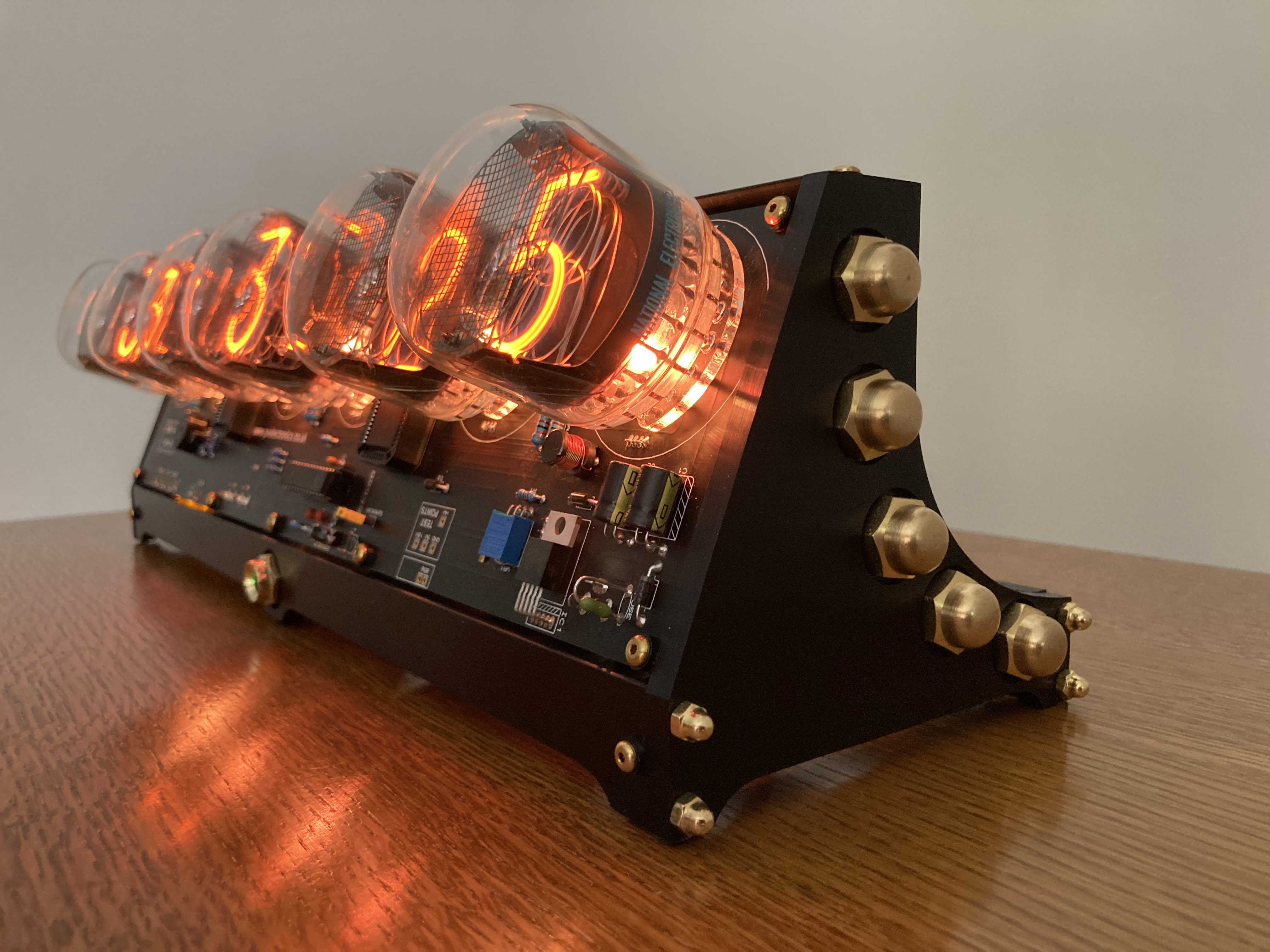
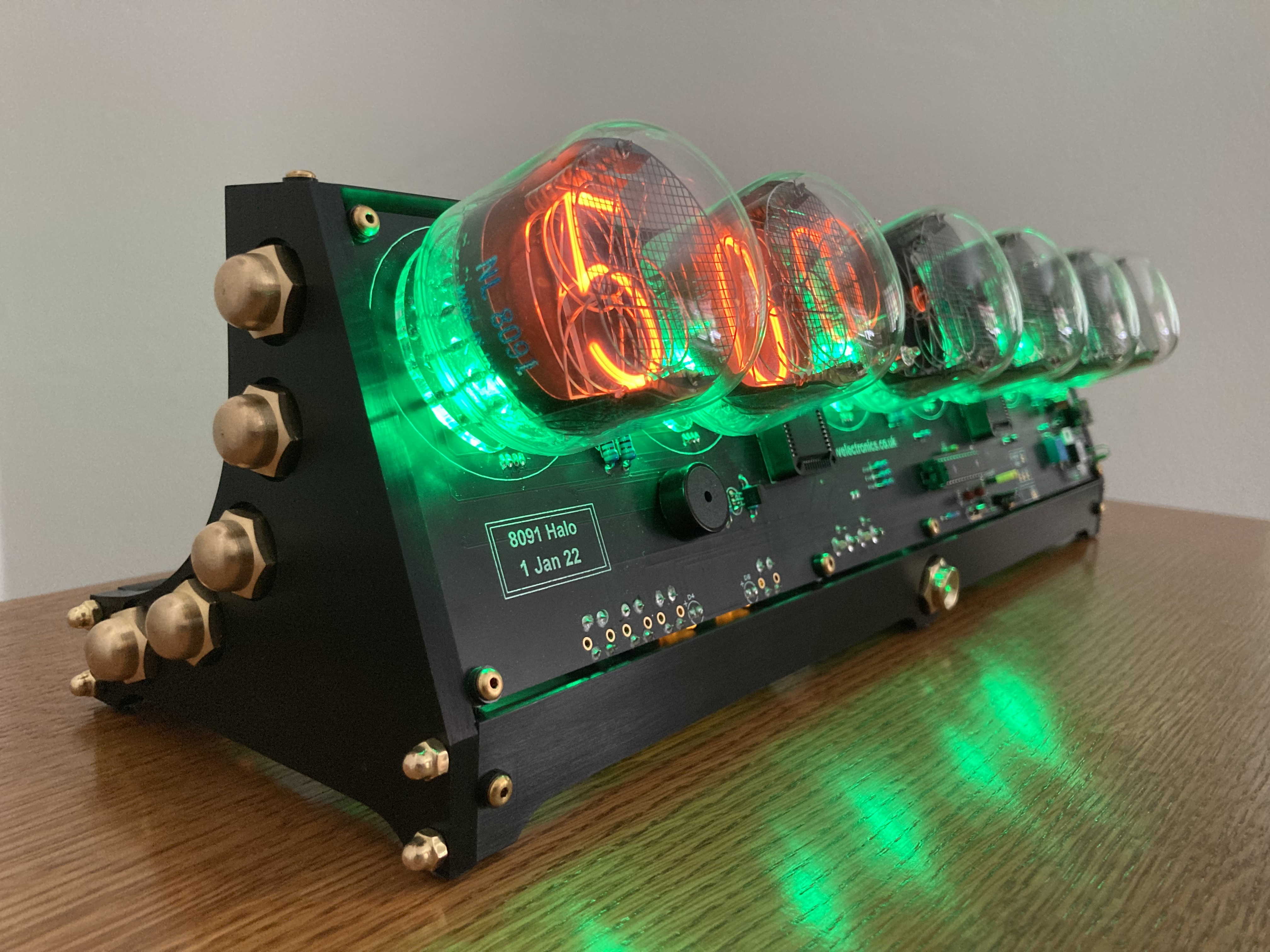
NL 8091 Angle Deck Nixie
NOT AVAILABLE FOR SALE
This clock was a one-off and a labor of love to build.
Thank you for your interest in my Nixie Clock creations. I hope Carl Ott and I continue to be inspired to create more and more as we move into this whacky ( wait, more than whacky) future !


Now, for you guys and gals that like to know how stuff is done, here are some build PICS showing how I did it:
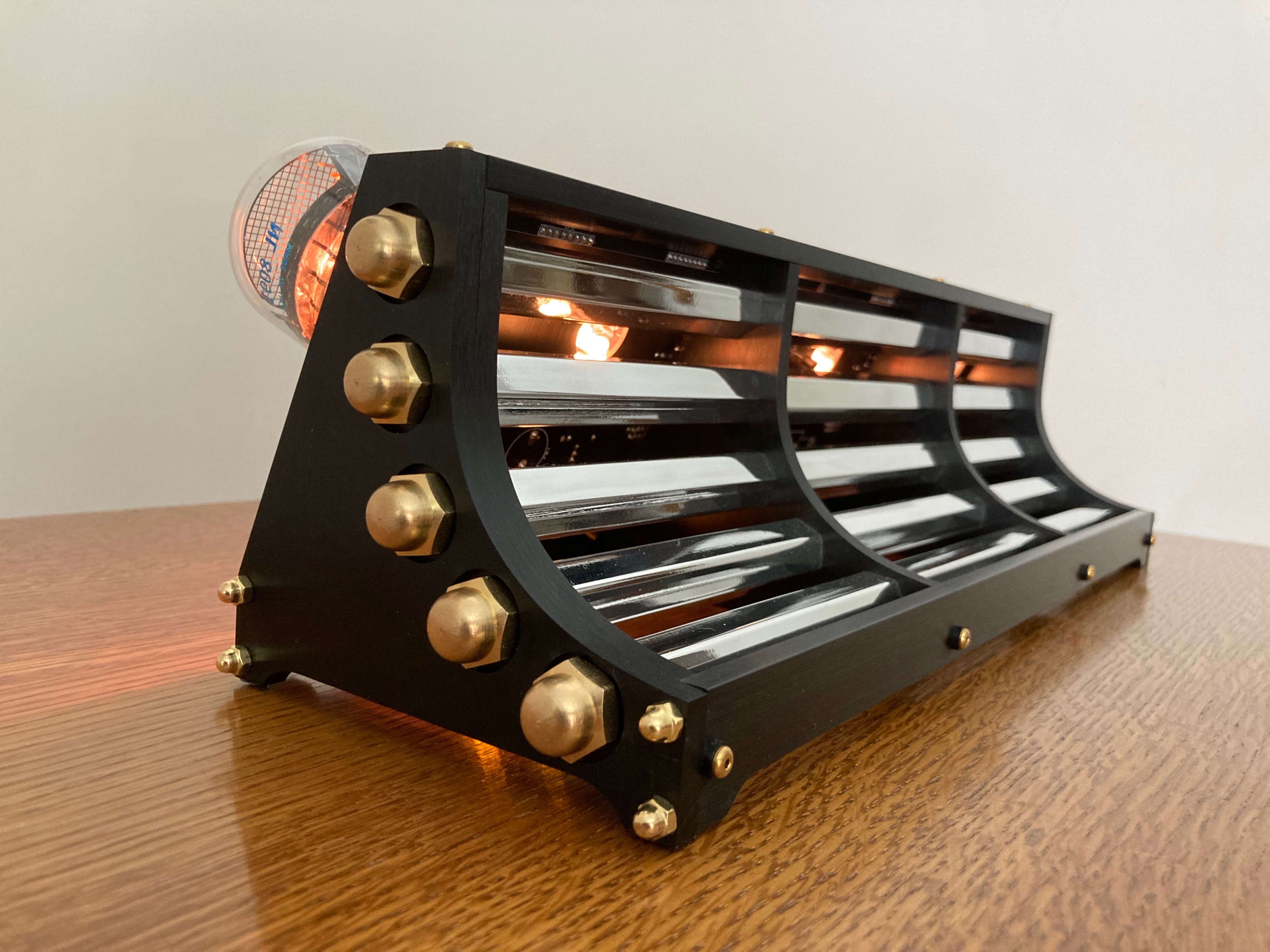
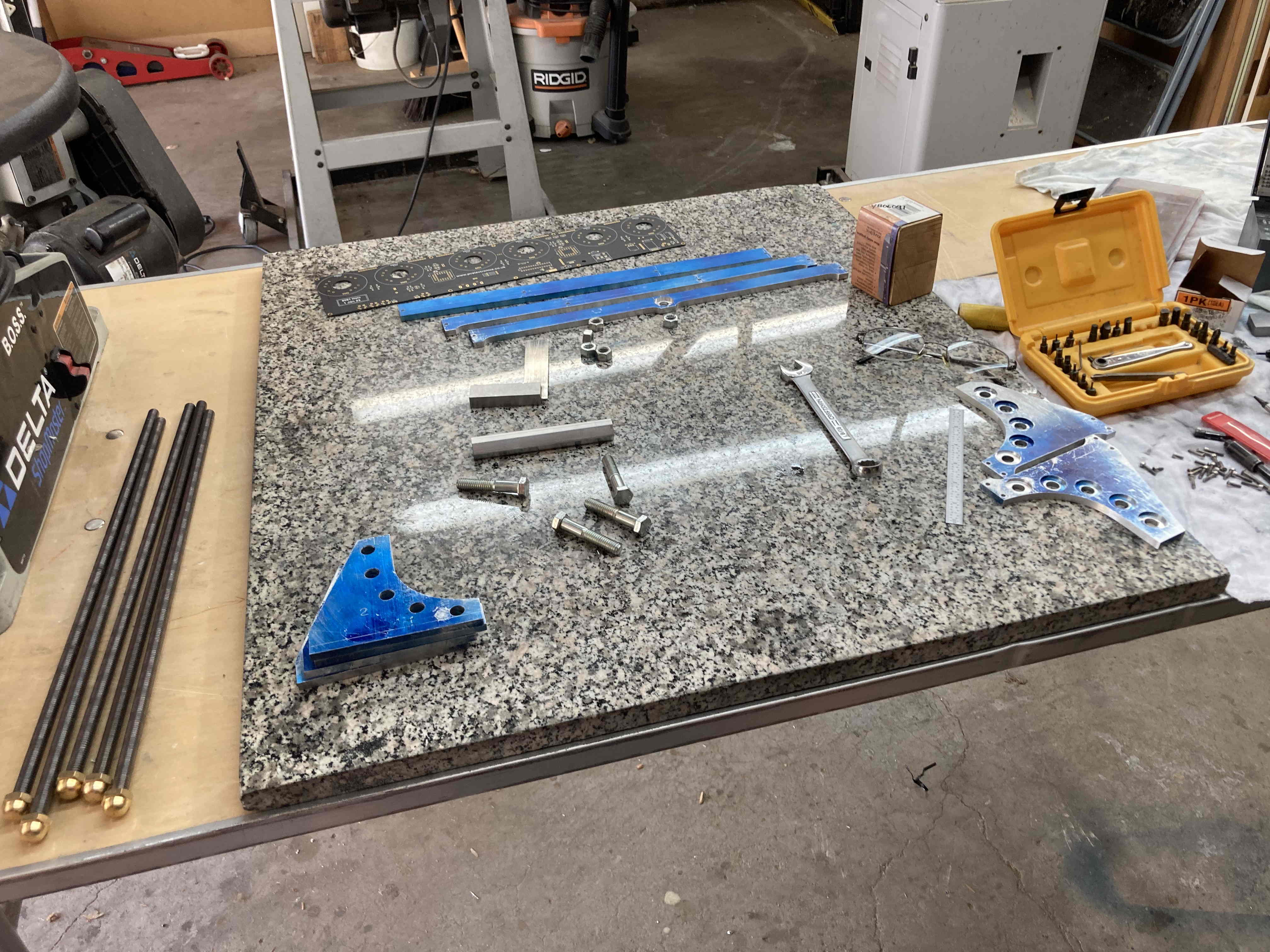
This clock case/enclosure was probably the mostly challenging of all of them I have built to date and took the longest. It is all hand done, out of 1/4” 6061 aluminum plate. Tools used were a Delta 12” Disc Sander, 6” metal cutting band saw, a spindle sander, a 20” Delta 70-200 Drill Press and various grit sanding blocks. All sections are #4-40 drilled and tapped and the uprights through-bored to accommodate five 3/8”-16 Stainless Steel threaded rods running the length of the clock. The small brass headed cap nuts are actually #4-40 screws that I fashioned by inserting and epoxying #4-40 hex head screws into the nut then cutting off the heads of the screws. Worked great! Curved section in the rear was rough cut on the band saw and finished on the spinal sander. (a lot of work! ) All pieces were hand sanded then anodized pearl black and 5/8” Hex Stock in the rear was polished by someone that really knows what they’re doing. (and that ain’t me) The outfit I use out here is V&M Polishing in Chatsworth, CA. Anodizing is by LNL Anodizing in Sun Valley, CA. Both of these companies do wonderful careful work and are honest and fair.
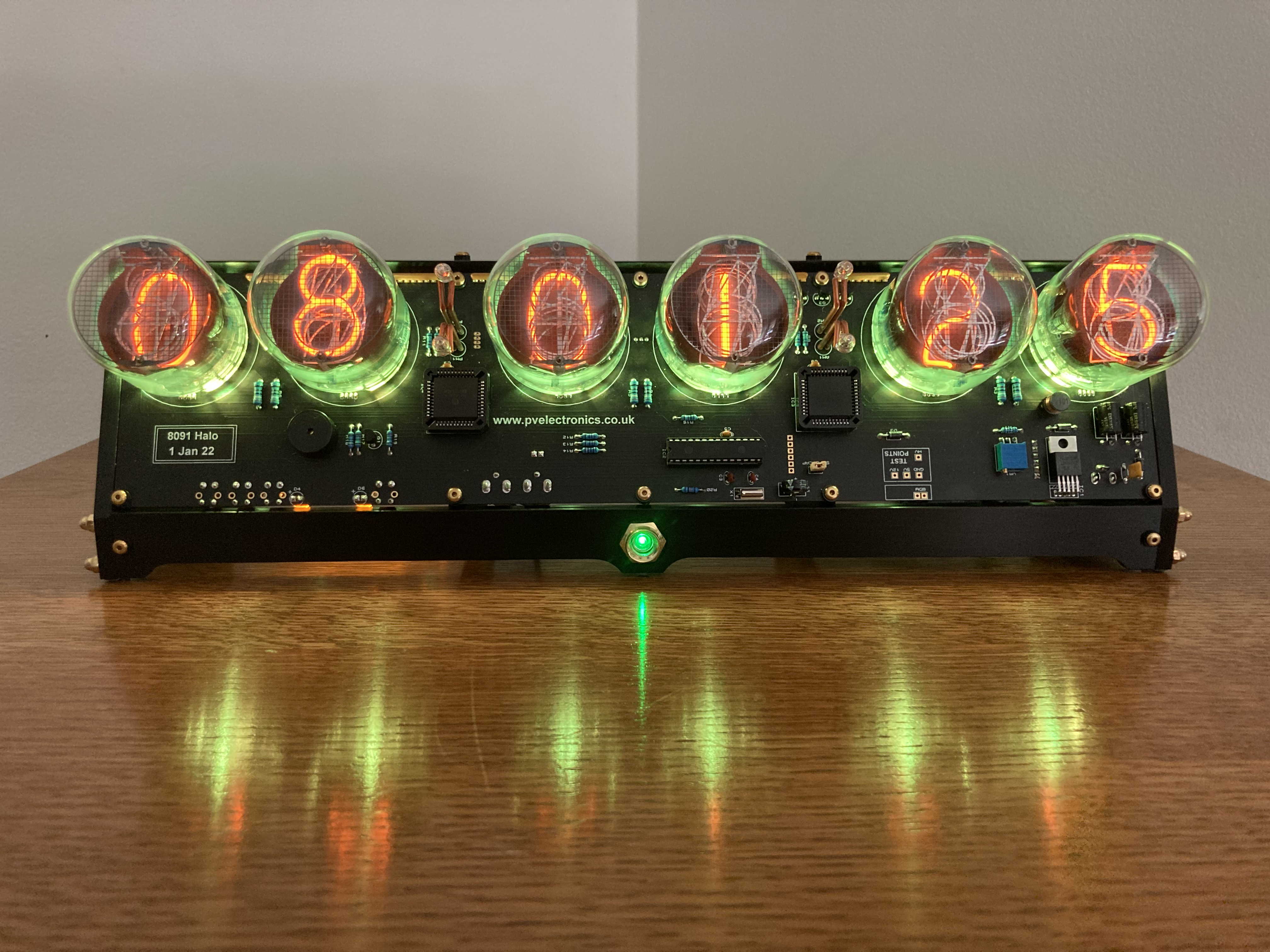
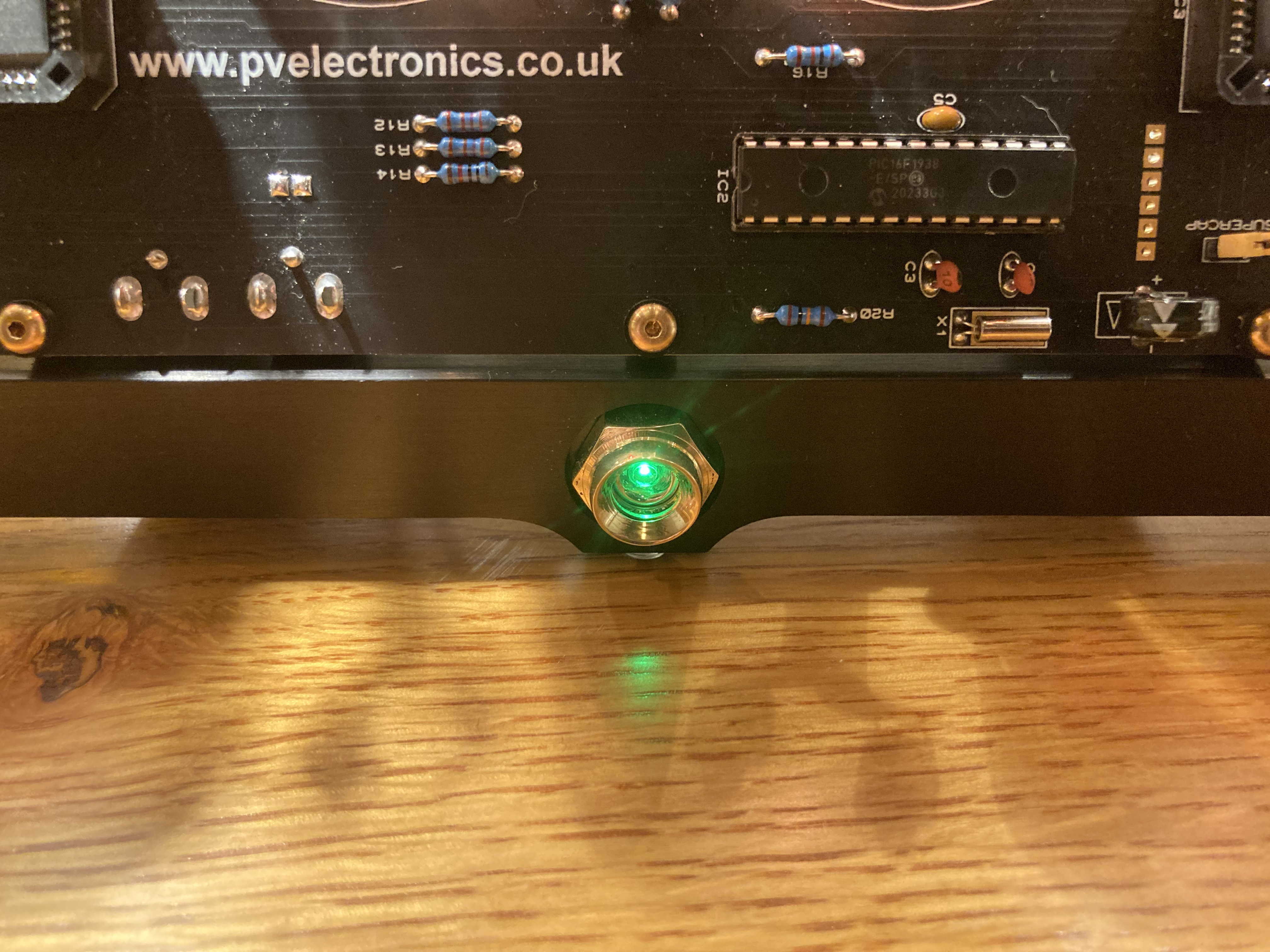
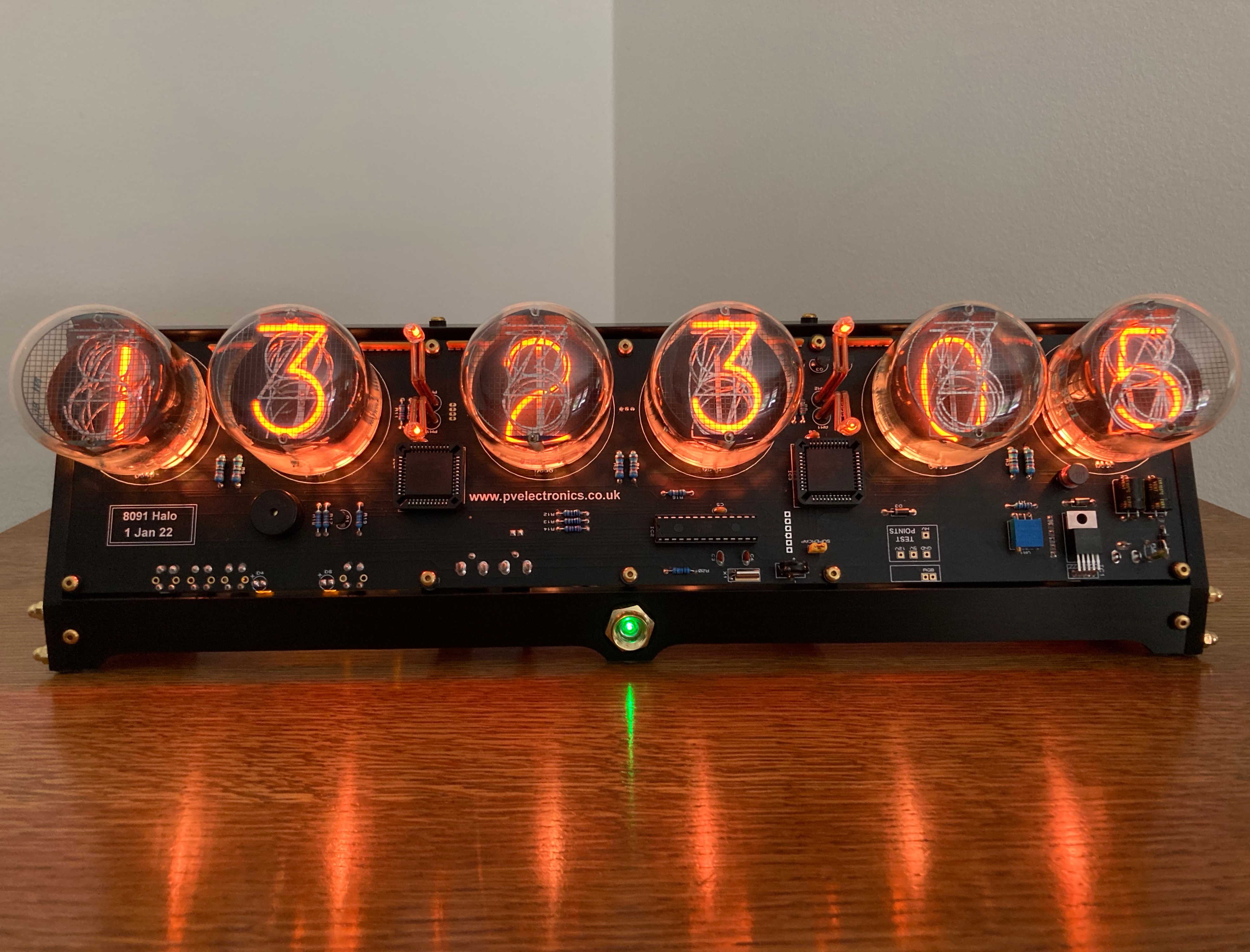
The electronics are obviously by Pete Virica. I did some minor mods ie; relocated the GPS lock LED with flying leads to the front of the clock in the center of the brass doo-dad you see nicely lit. That doo-dad started out life as just another 3/8”-16 brass cap nut until I bored out the center and chamfered the opening to accommodate a 3mm LED from the rear. It is held in place with a 3/8”-16 Hex head SS cap screw whose center was also bored out for the LED.
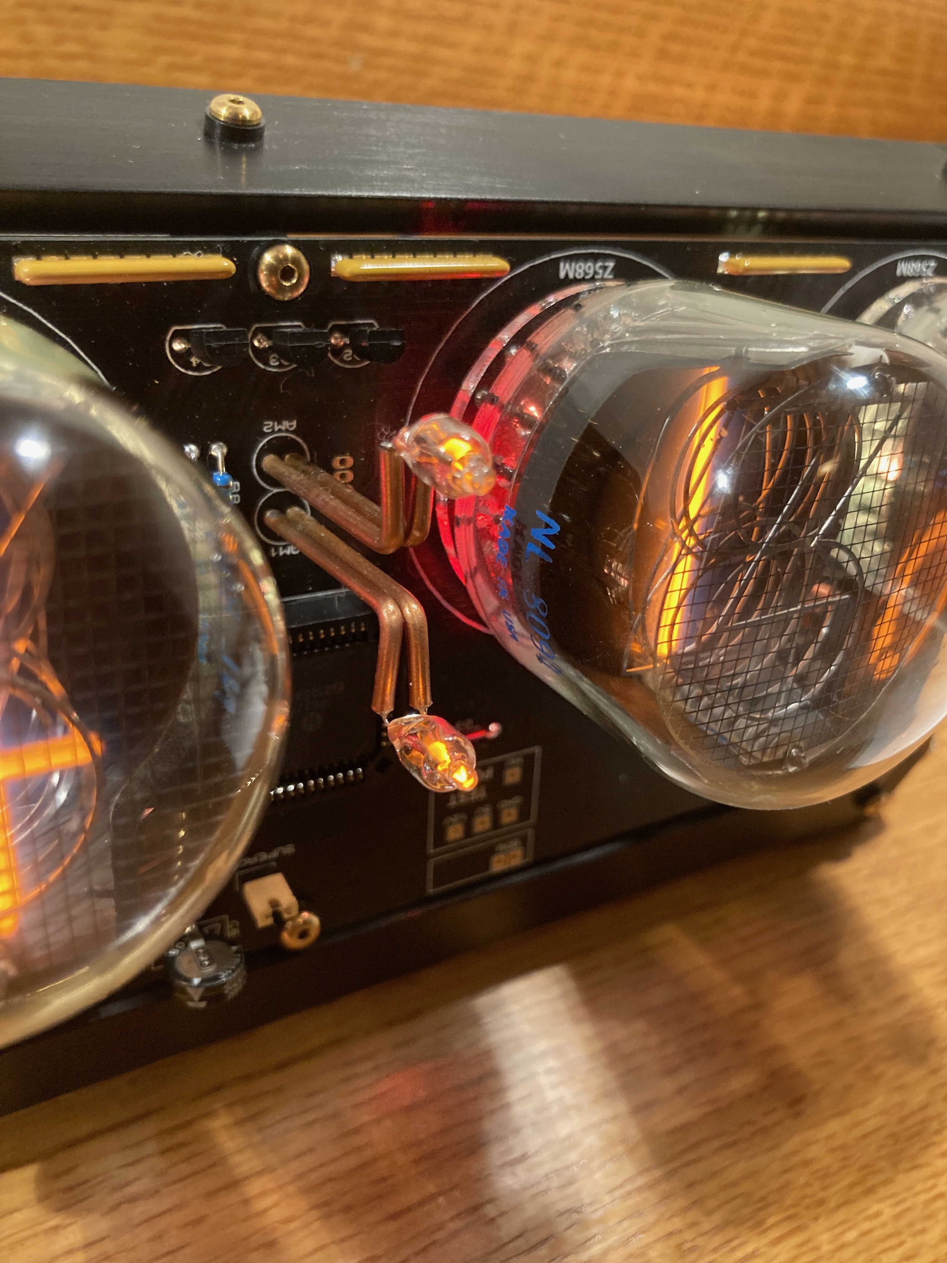
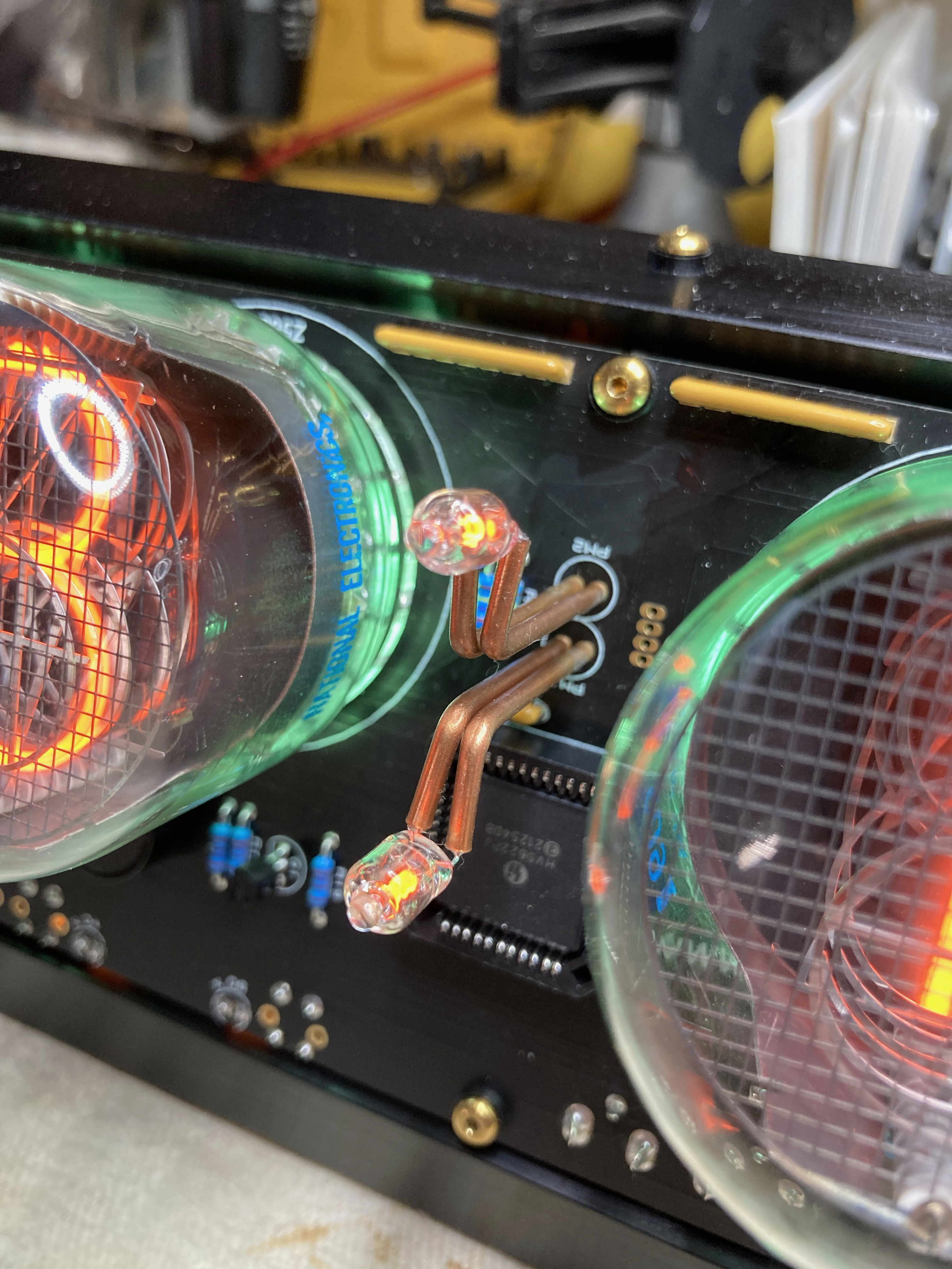
Colon towers are 1/16” copper tube sheathed with clear heat shrink and cold-bent to achieve a 1” separation between the 2 NE-2’s. Steel .032” piano wire was soldered in the anchor-end of each piece of tubing, then soldered into the opening in the PCB for added strength. Changed the quad resistors to yellow colored versions for a little added pop.
Now, it’s off to the Anodizer and Polisher (for the Hex stock)
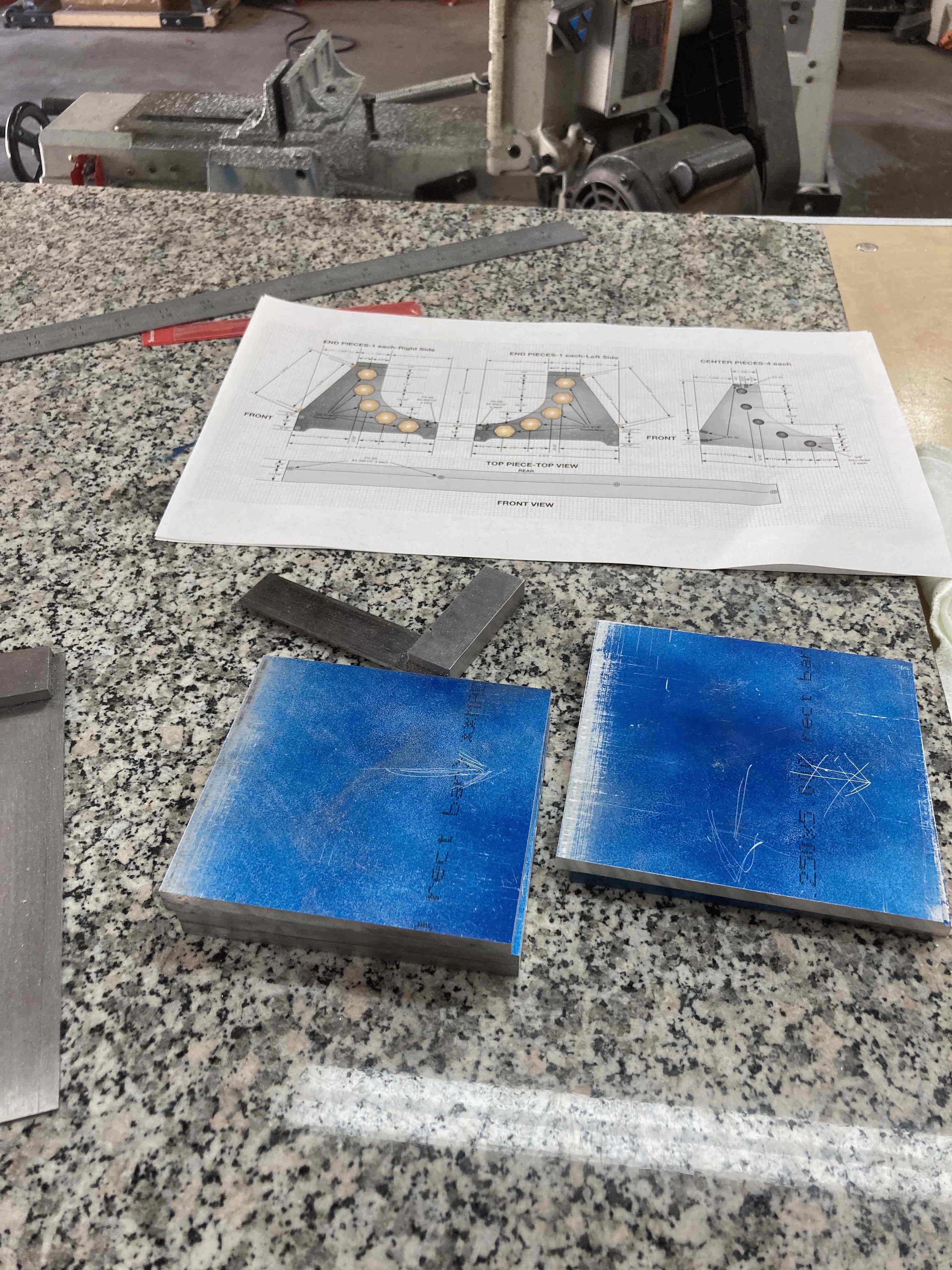
Blanks cut and sized to 0.005” tolerances
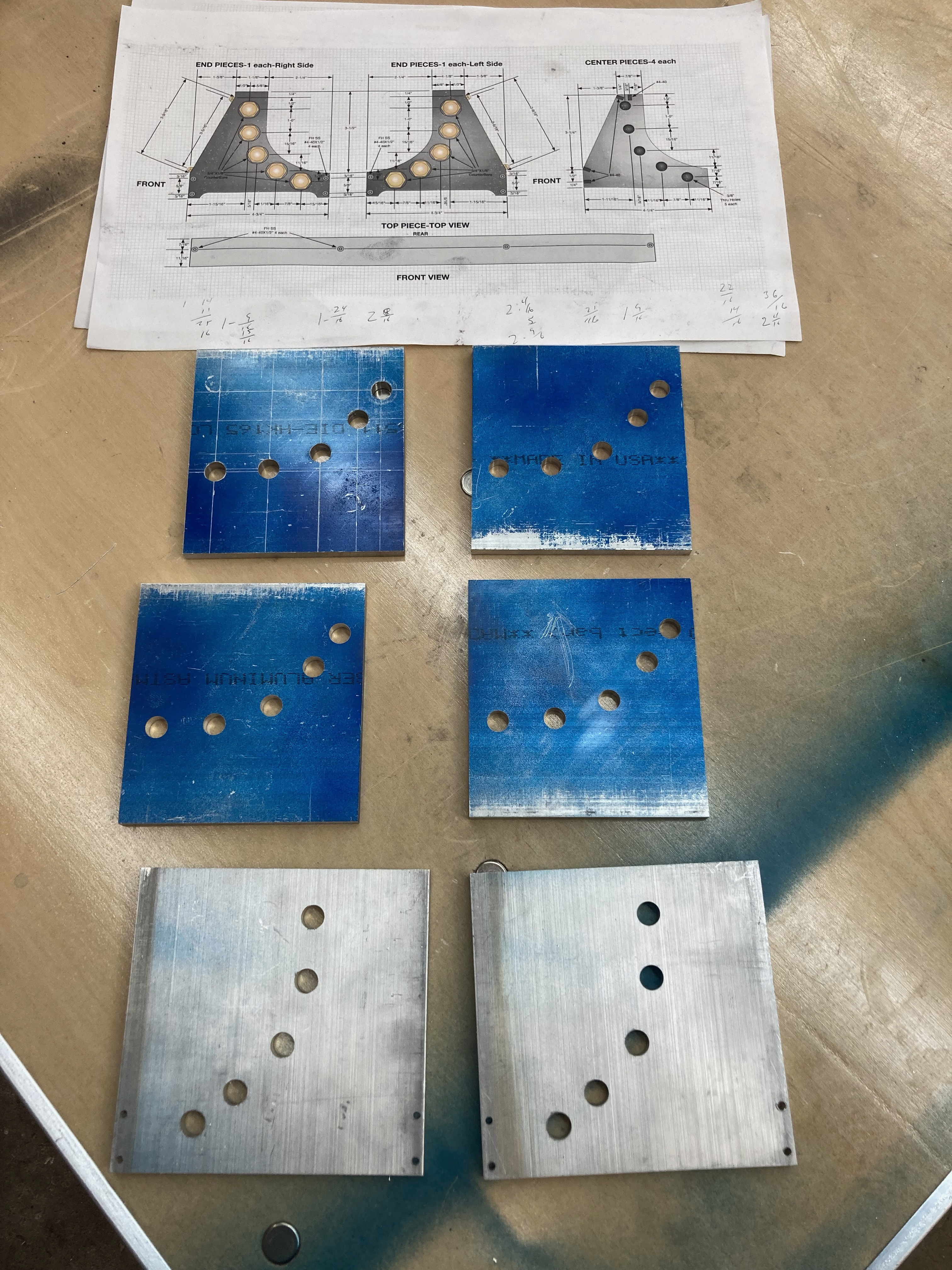
Blanks through-hole bored simultaneously
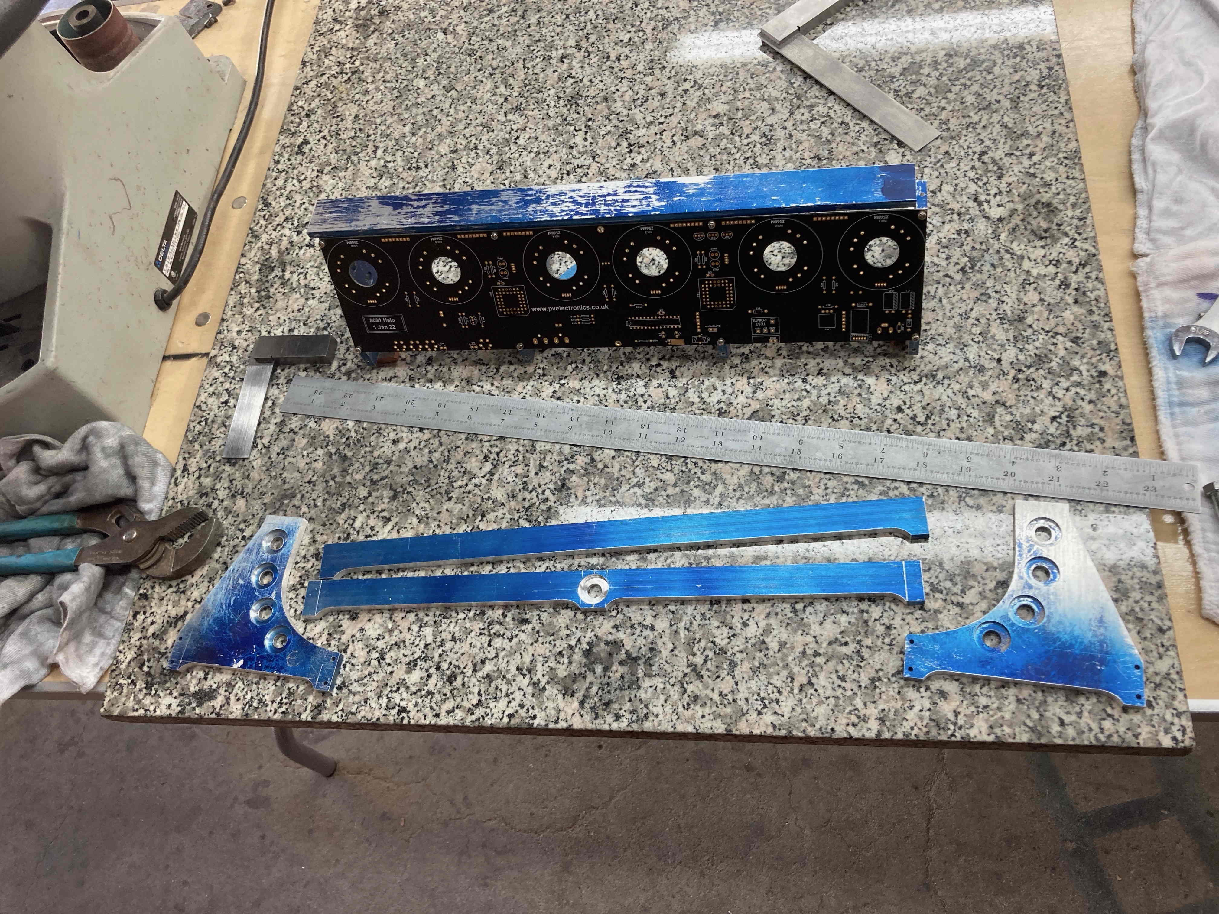
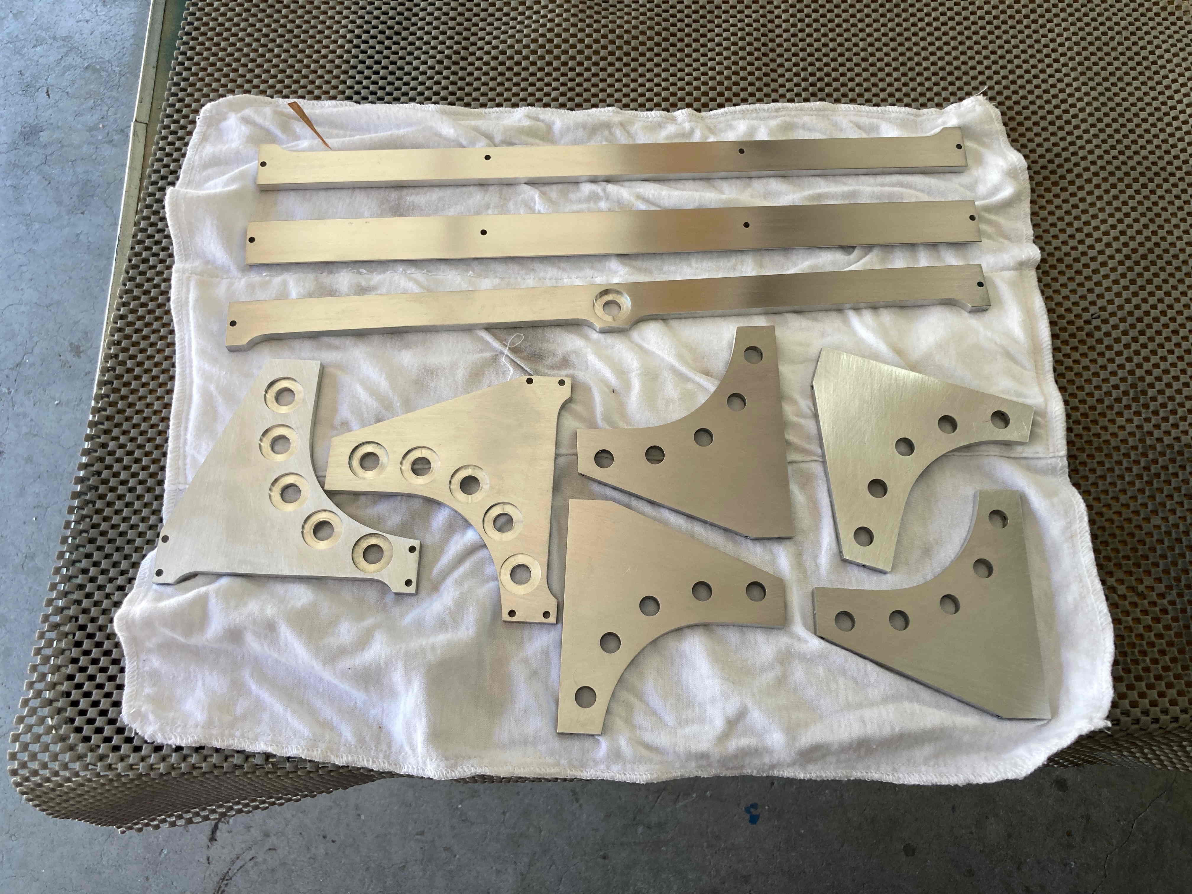
Holes counterbored, angles and curved profiles rough cut and sized
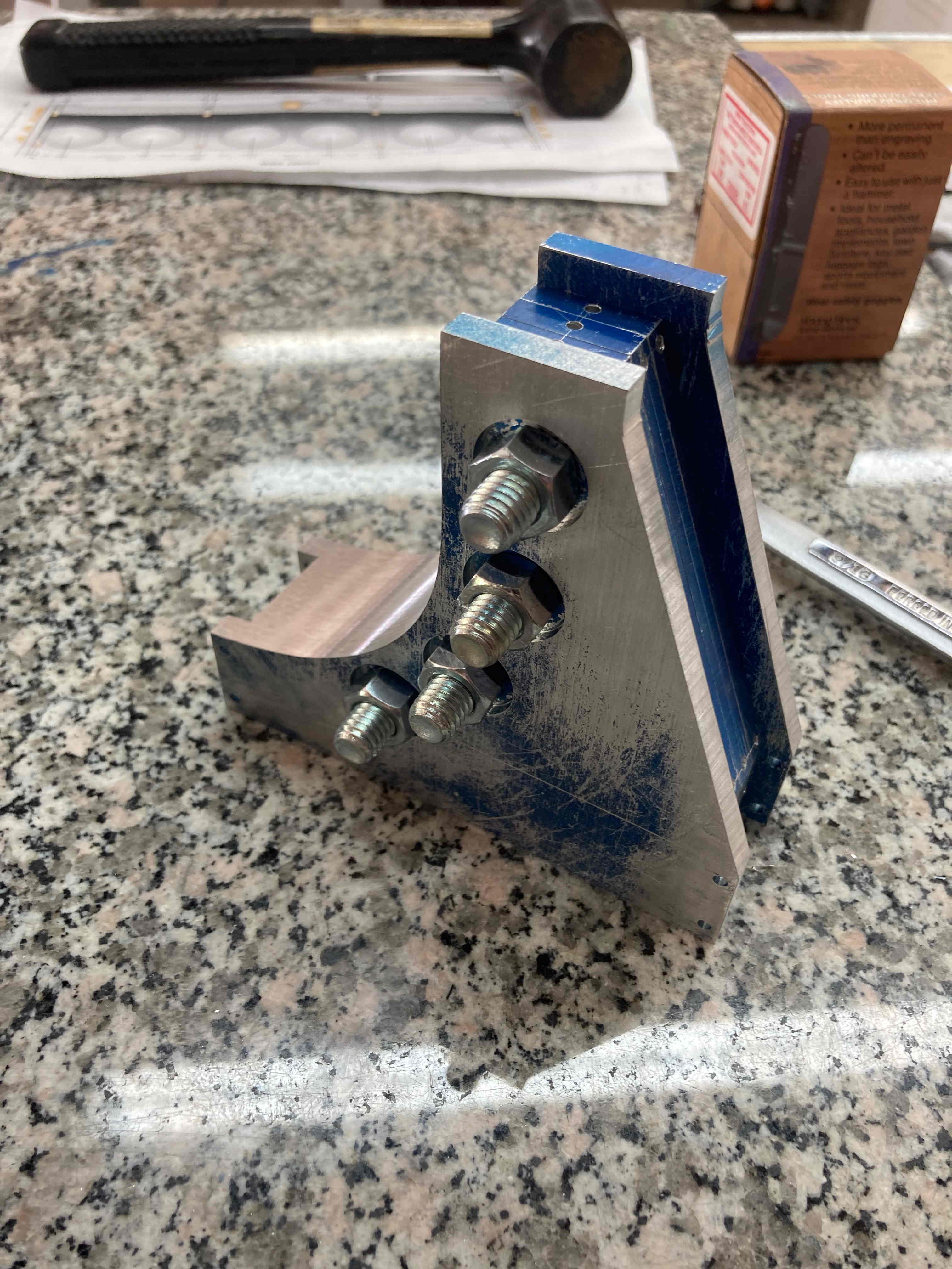
Dry fit checked after all #4-40 holes drilled and tapped
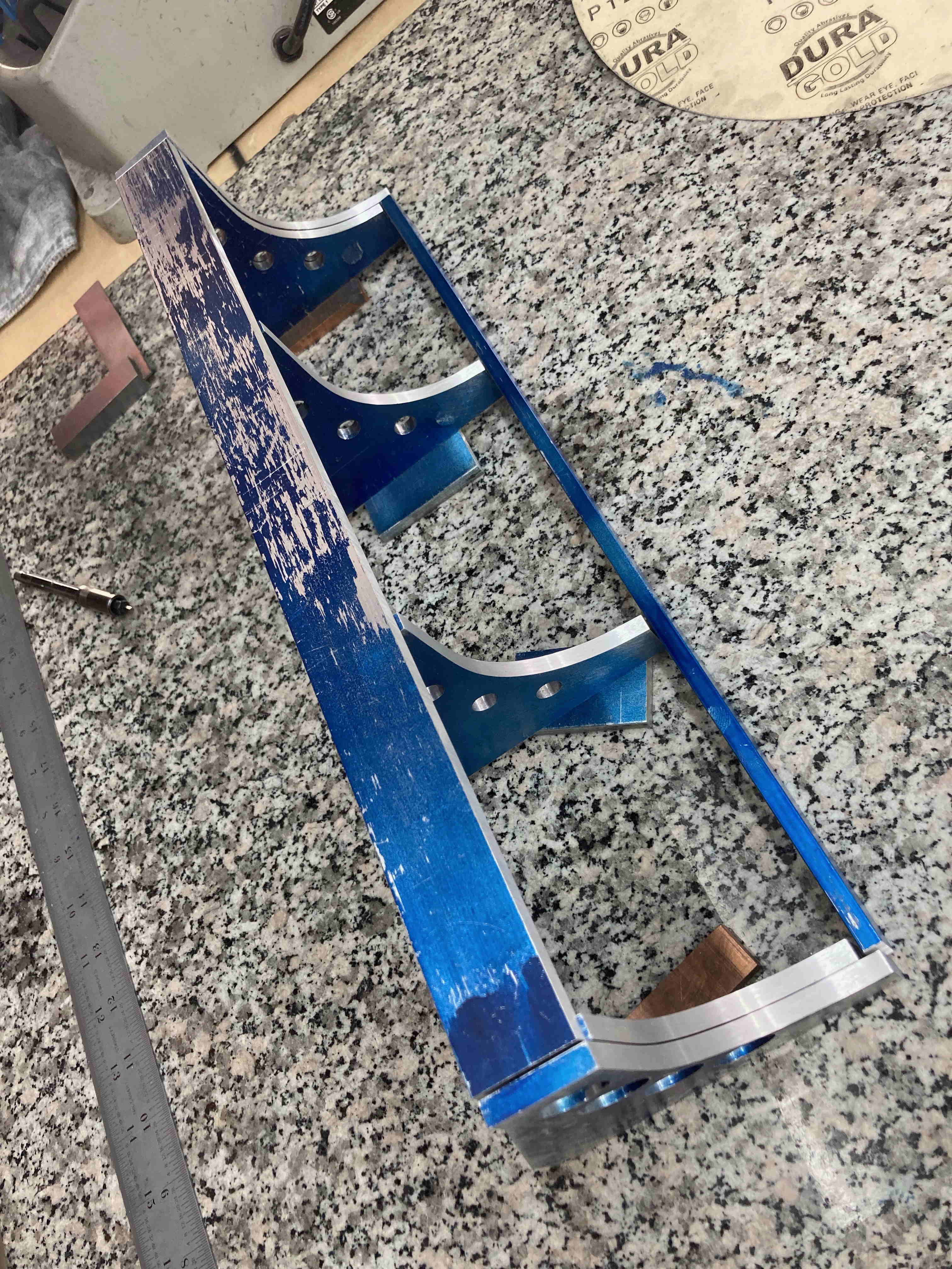
Lower feet relief contours cut, sized, and finished.
Parts readied and cleaned for anodizing and polishing.
Many intermediate steps have not been show here. This is a very abbreviated version of all that was required to create the end result. Thanks for your interest and remember:
NEW MOD SIX WILL BE RELEASING SOON!! !
Michael Barile
BadNixie.com LLC